LoD3 Modeling based on Mobile Laser Scans
Preliminary
Software
Requirements
Useful Plugins
Input data
Within this workflow pipeline following datasets were used:
XYZ (simplified pointcloud =< 150 000 points to assure SketchUp efficiency)
CityGML (selected input LoD1 to simplify modeling tasks later on)
possibly already created adjacent LoD3 buildings
Data import
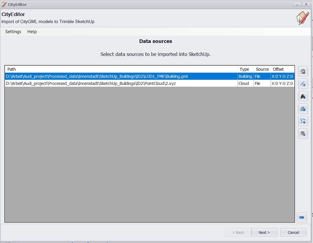
After installing and activating SketchUp and the CityEditor plugin, the import of datasets is possible. Select CityEditor Importer to run the importing window.
Click on the building icon at the top-right to add CityGML objects (formats like .xml, .gml, .shp, .dxf, and other avalaible). It is possible to add single files (under File…) or several (Directory…).
After a successful selection, the building dataset should be listed in the gray area of a window.
A similar operation should be performed for adding point clouds. The plugin allows to add point clouds only in .xyz or .csv format and number of points should be lower than 200 000 (for best performance =<150 000 were used within this tutorial). Instead of building an icon you should choose a small squares icon, second from bottom-right. Again, there is an option to add a single object or a whole directory.
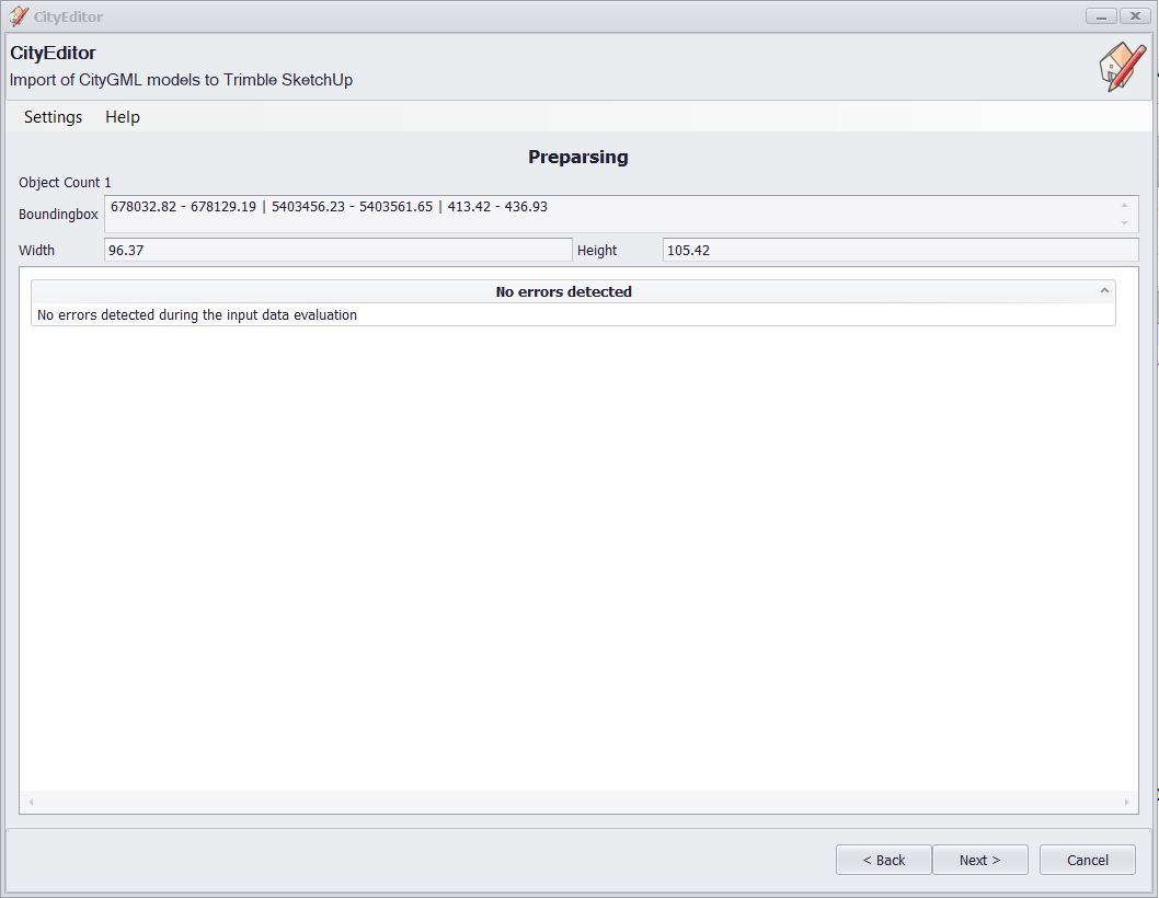
Click Next. Then, in section Preparsing click Next again to pre-validate your data. Depending on data it can take to several minutes, the process can be tracked in the process bar. Preparsing results contain information about the model bounding box, width, height and list of errors. At this point, you can check whether your data are in a proper coordinate system and roughly estimate the position of your model.
Click Next to proceed.
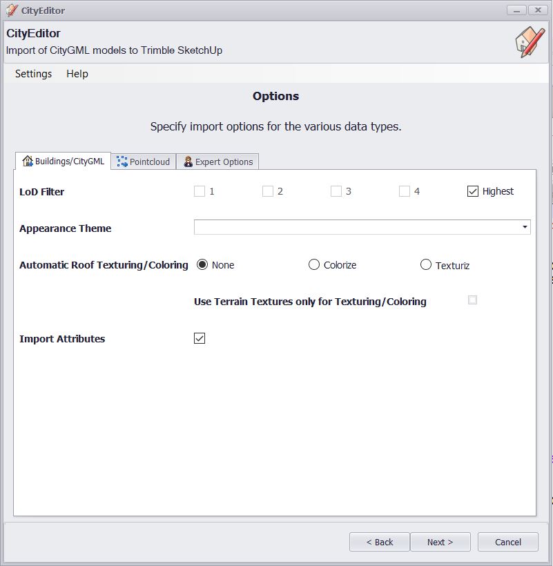
Options window contains 3 sections: Buildings/CityGML, Pointcloud and Expert Options. If more types of datasets are chosen the sections expand accordingly.
Tick the Highest available to pick all available LoD within our dataset (in this example number 1 is sufficient for building in LoD1).
To load an appearance of buildings select Appearance Theme - in this example there are no textures available.
Automatic Roof Texturing/Coloring is set to None. However, it is possible to automatically colorize (Colorize) Roof surfaces or put a texture (Texturiz) based on WMS (like OSM) and buildings coordinates at the rooftop. In the creation of LoD3, it is mostly not relevant.
To import attributes of objects tick Import Attributes.
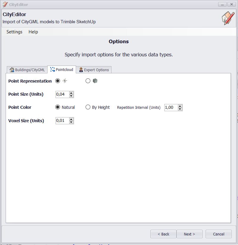
Go to the Pointcloud section now. Here you can select your preferences regarding point cloud representation - plus or cube (Point Representation).
Moreover, Point Size in units of a map (meters in this example - depends on the coordinate system of input data) can be set as well as colour (by Height or Natural) and Voxel Size.
Values presented in a screenshot assure good performance and minimize further simplification of point cloud by a plugin. More about Voxel : (Voxel on Wikipedia, CityEditor Manual )
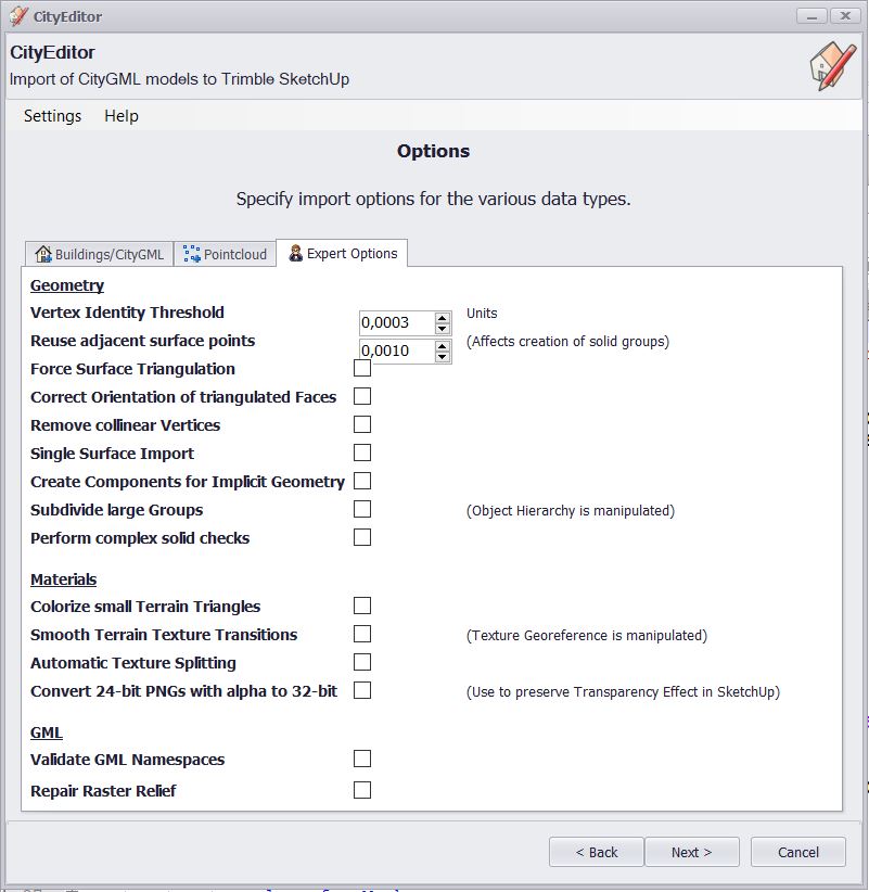
Expert Options bar is relevant only if you want to import higher detailed buildings or materials. Also, there is an option to validate GML Namespaces at this point. The default values are sufficient to proceed.
Now, you can click Next to continue.
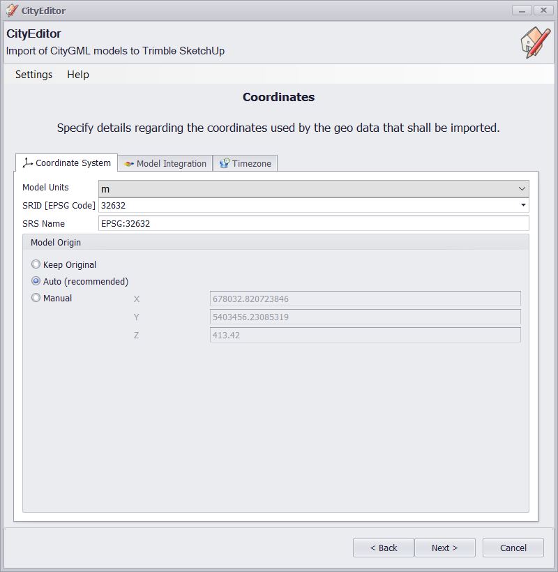
In Coordinates window you can check your coordinate system (Coordinate System section) or integrate your data with already existing SketchUp project (Model Integration) and set timezone (Timezone). In this example, the plugin reads everything automatically.
Click Next to continue.
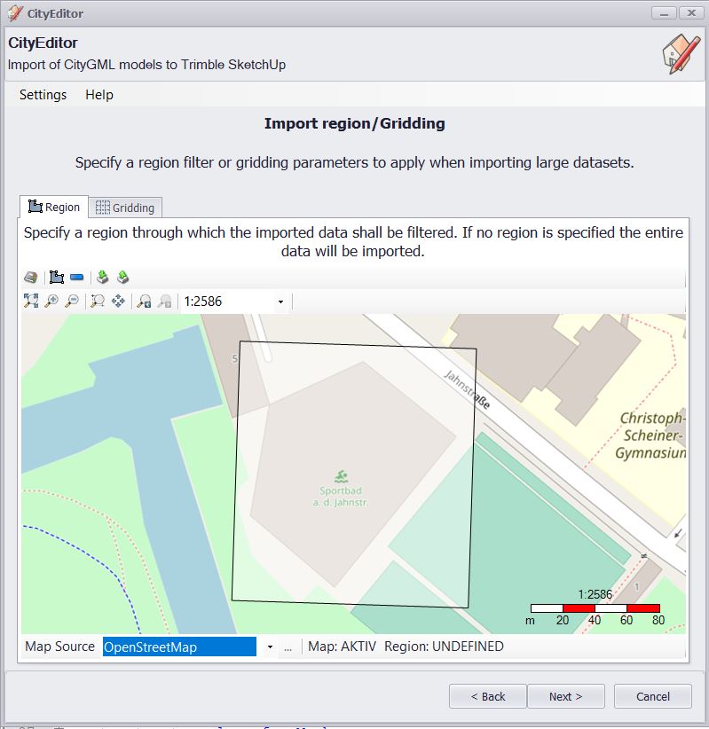
The next window allows us to filter out only relevant data from the whole dataset simply by Region or Gridding definition. This part also can serve as a preview of data extend thanks to the option of base map selection (Map Source), here OpenStreetMap selected. Filtering at this point is not recommended - it is better to prepare data before importing it to SketchUp.
Click Next to continue.
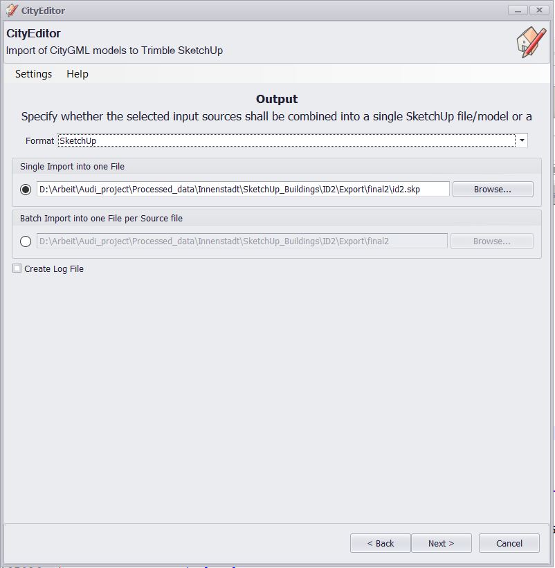
In the following window, you can specify a saving path. You can tick the option below to save log file as text which can be found in the same folder.
Click Next and then Finish to load data.
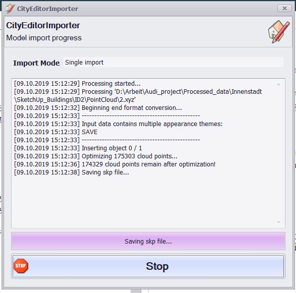
Steps performed by the plugin are displayed in a window.
Modeling
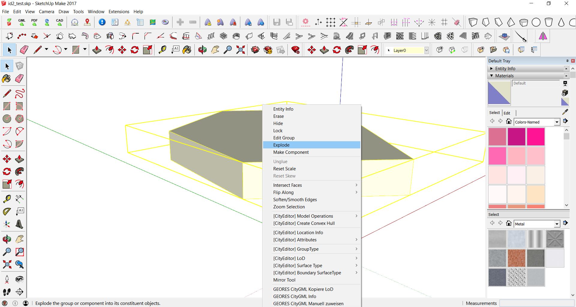
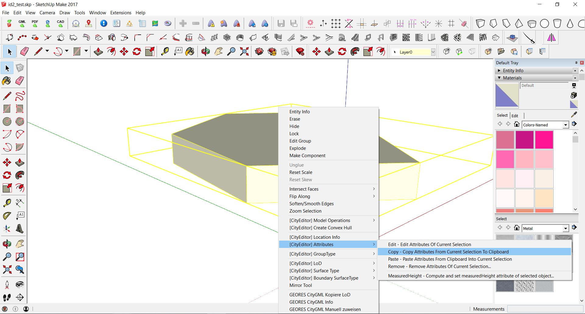
The LoD1 building and the point cloud are imported as a starting point for the modeling. First, it is relevant to copy attributes from the LoD1 building (Right Click-> Attributes -> Copy to Clipboard). At the end of objects modeling, the building is merged in a group and the attributes can be reassigned.
Further modeling should be done with the aid of a point cloud, an external preview of a point cloud and photos or mesh from Google Earth Pro. Additionally, the website Mapillary provides crowdsourced street-level images. Not every part of a building has to be done from scratch. A wide repository is available on SketchUp Warehouse where tiny and big elements can be downloaded.
Moreover, the SketchUp community (SketchUp extensions) offers a lot of plugins tailored to the user’s needs. Some of the most interesting for building modeling are: - Chris Fullmer Tools, Component Onto Faces - bit tools 1001 - Weld
Walls and ground surface
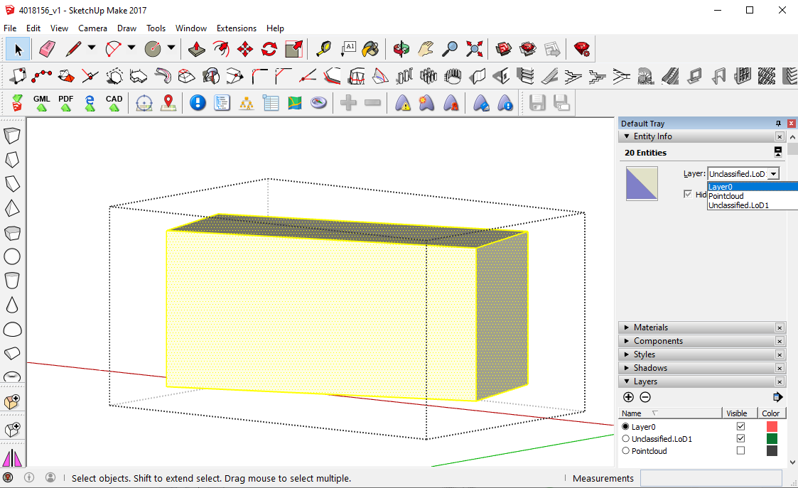
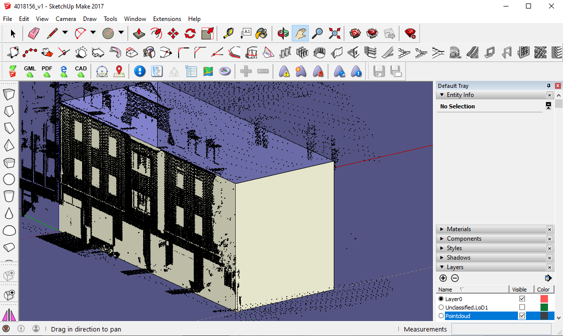
The walls and the ground surface are modeled based on the LoD1 building and the point cloud. The layers which are created automatically are Layer0, PointCloud and Unclassified.LoD1. In a later step, when assigning the building components to CityGML, further layers are created automatically. Apart from this, it is not required to create additional layers. Layer0 should remain the current layer during the modeling.
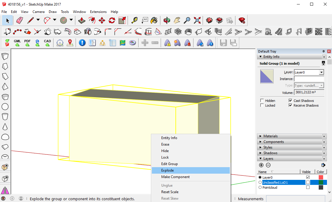
At the beginning, the layer of the point cloud can be hidden. Click on the LoD1 building and copy it (Edit -> Copy) and then paste it (Edit -> Paste in Place). Edit the new one with Double Click, mark all entities with Double Click and assign them to Layer0. Explode the LoD1 building on Layer0.
The layer Unclassified.LoD1 can then be hidden but contains the original LoD1 building as a backup, in case it is needed later. The other one can be changed while modeling the walls and the ground surface.
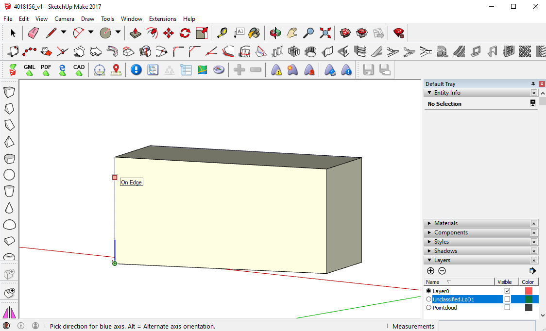
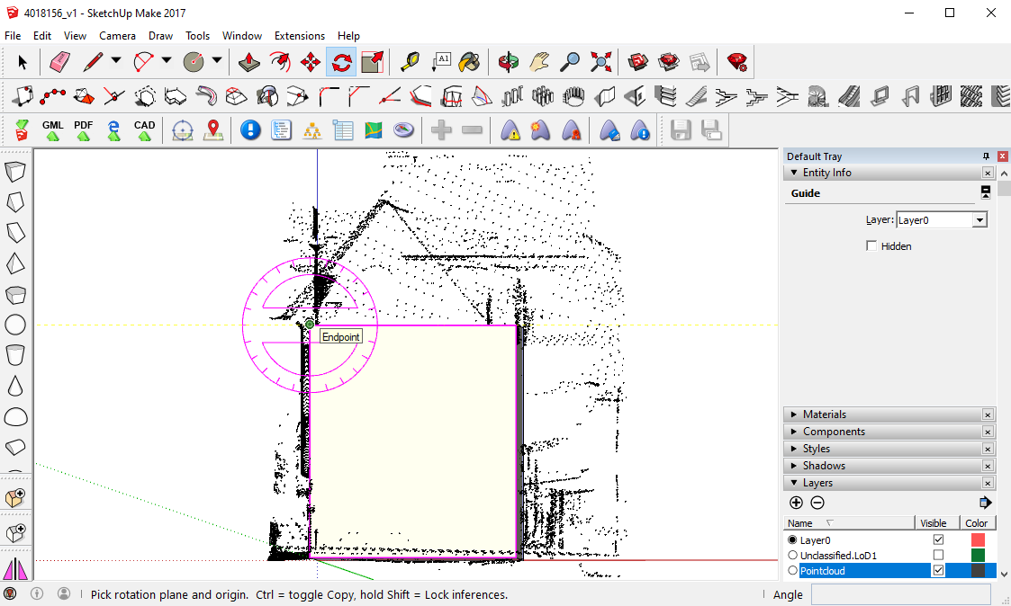
Choose one of the edges of the LoD1 building and position the coordinate system there, so the origin is at the lower corner and the blue axis lies on the vertical edge (Tools -> Axes). This is helpful for the modeling, as the edges of the building can now be drawn parallel to the blue axis.
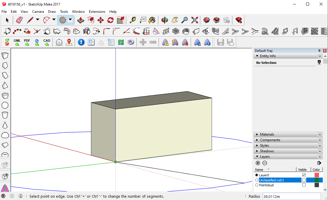
Use the Circle tool to draw a coplanar surface for preparing the ground surface. The center of the circle is the origin of the coordinate system from the previous step and the circle is perpendicular to the blue axis.
Now use the Extend Edge to Edge or Face tool for all the building edges, so they reach the circular ground surface.
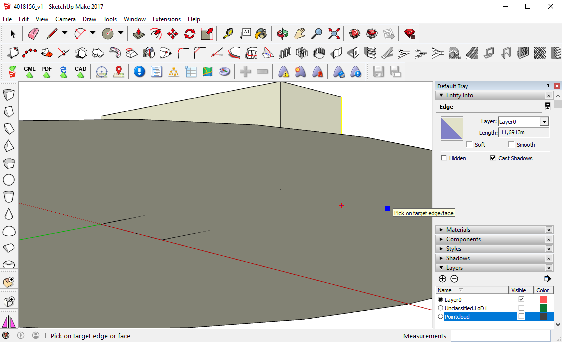
Change the perspective, so you look to the ground surface from underneath and draw lines between the end points of the edges. These lines lie on the ground surface and mark the position of the building edges.
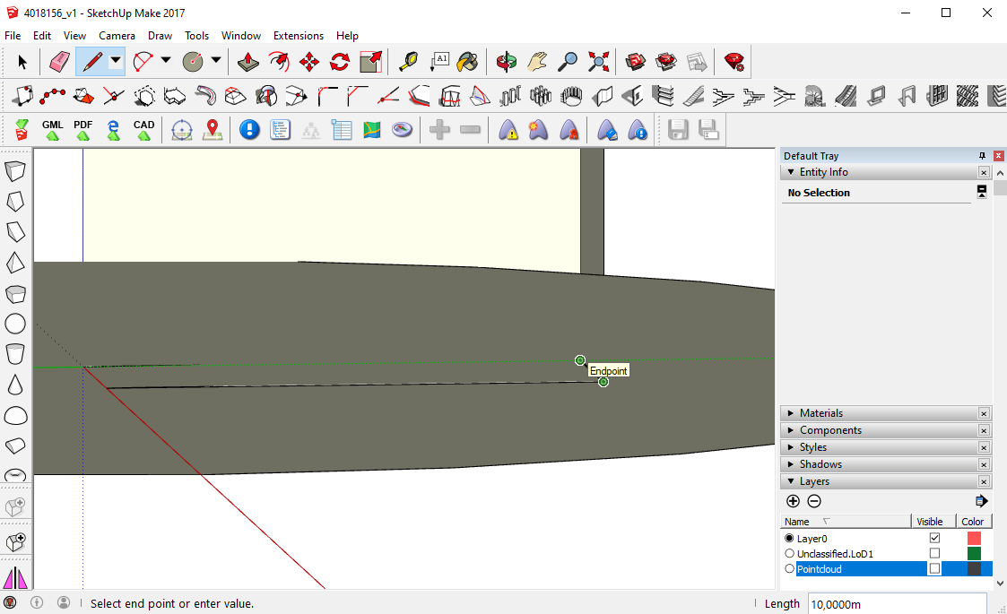
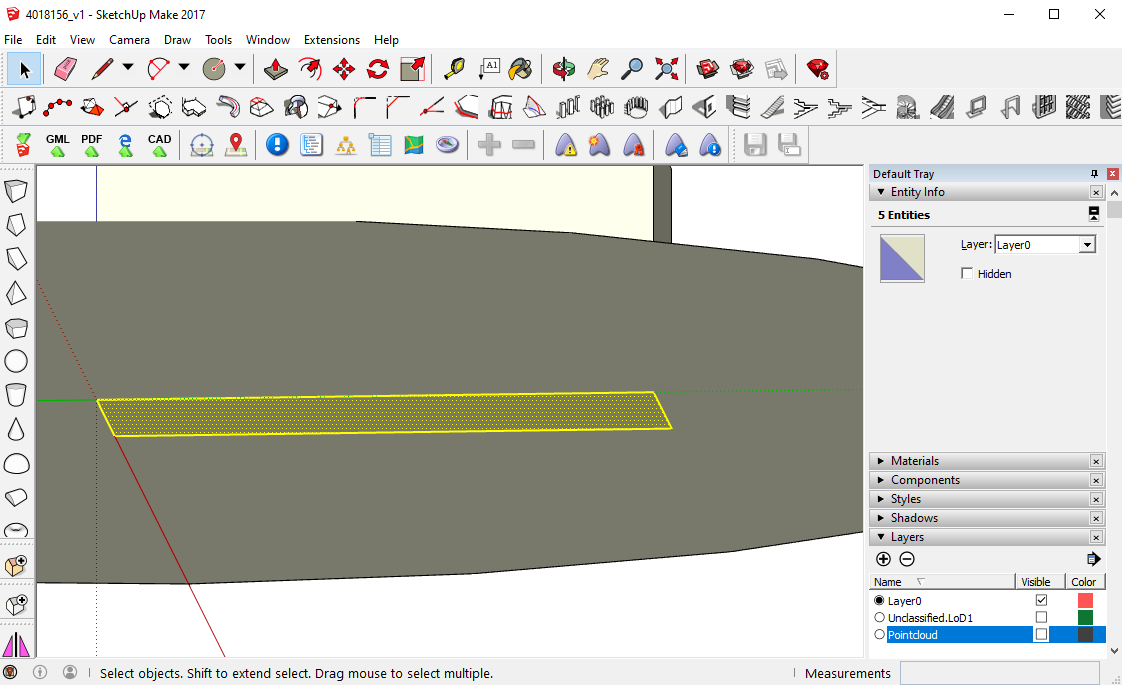
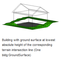
Erase the edges of the exploded LoD1 (on Layer0) and the small edges from the Extend Edges command, so you have no vertical lines any more, but only the horizontal lines of the ground surface. Also, erase the upper horizontal lines of the exploded LoD1. On Layer0 only the ground surface and the circular surface are left now. Next, define the level of the ground surface. Therefore, check the point cloud and derive the lowest level of the ground surrounding the building.
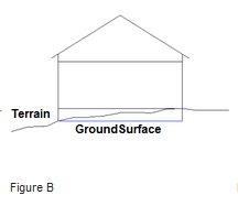
If the ground surface is not at the lowest level you move it along the blue axis, otherwise you can leave it in its position. The following illustrations from the sig3d guide also represent how the ground surface should be modeled. [sid3d]
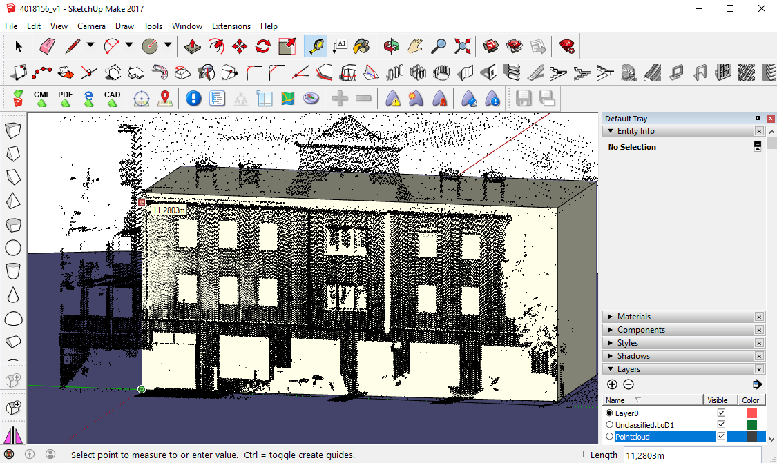
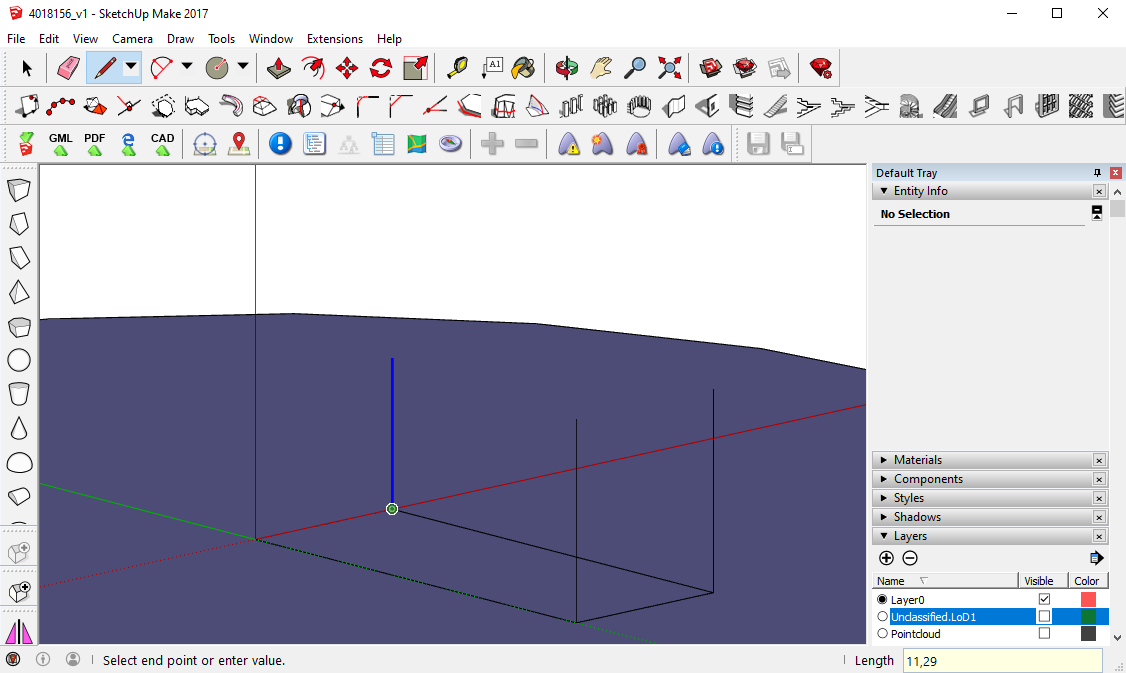
Compare the height of the edges of the LoD1 building with the point cloud (here, it is necessary to turn the Unclassified.LoD1 layer on again). Check if the edges correspond to the point cloud. The LOD1 building has one average height, so in few cases the corners of a building are not good represented (e.g. if the building has two parts with different heights). With the Tape Measure Tool, measure the height from the ground surface to the upper corners of the facade. Find an average height for all building edges. This value is then used for drawing all edges, so they have the same height (here e.g., 11.29m is used).
Now, from the lines on the ground, draw the new building edges, using the before chosen height.
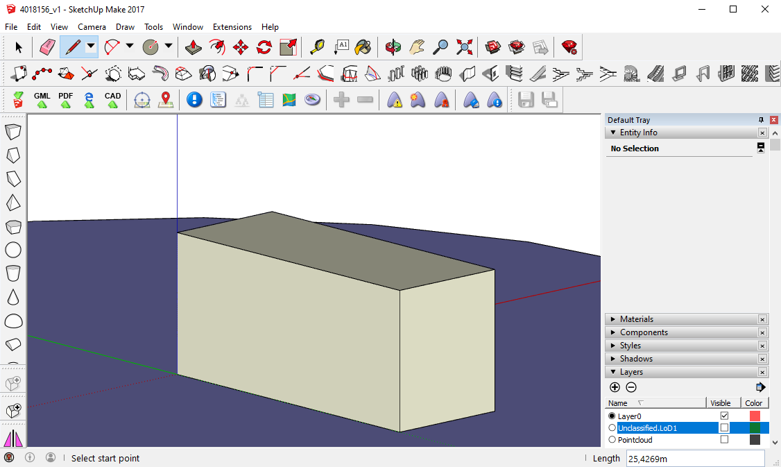
Draw lines between the upper ends of the edges. If everything went right so far, SketchUp automatically creates surfaces between the edges. They are the walls of the building.
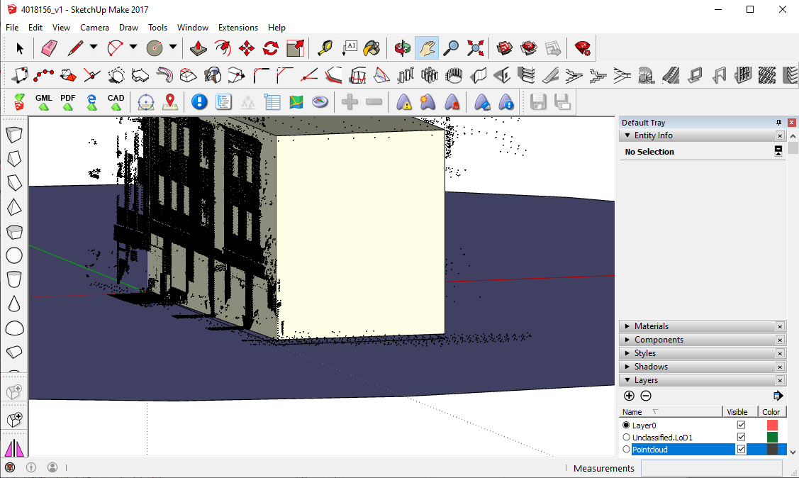
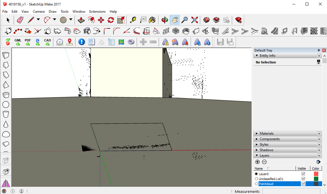
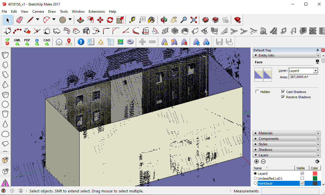
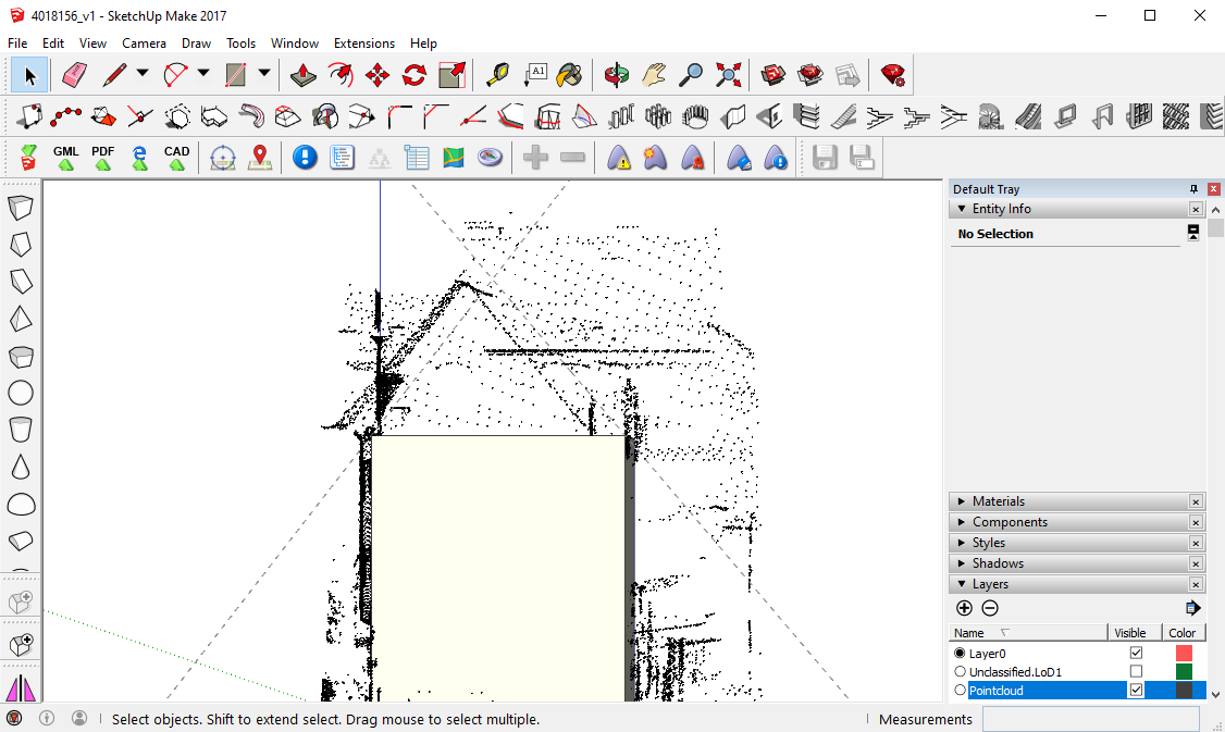
Now it is necessary to control, whether the walls are in an adequate position. You can erase the upper horizontal surface, which was created automatically, turn on the Pointcloud layer and from an aerial perspective check if there are many points, which lie behind the modeled wall. Approximately half of the points should lie before, half of the points behind the wall. It should be in a position so it is for instance possible to recognize the position of windows, etc.
If necessary, you can mark the wall surface, position a guiding line on the under perpendicular building edge and with the Move tool move the wall along the guiding line and adjust its position.
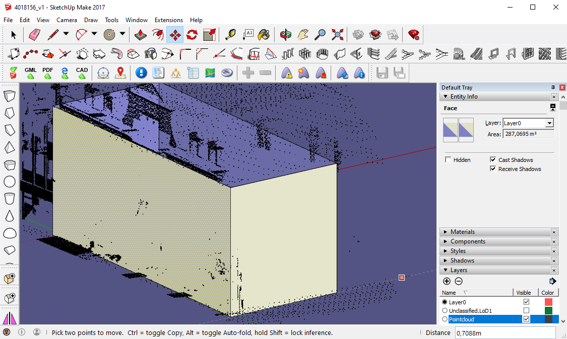
This should be controlled for the façade that fronts the street and eventually for visible flanking walls, too. Here, the position of the wall was not changed.
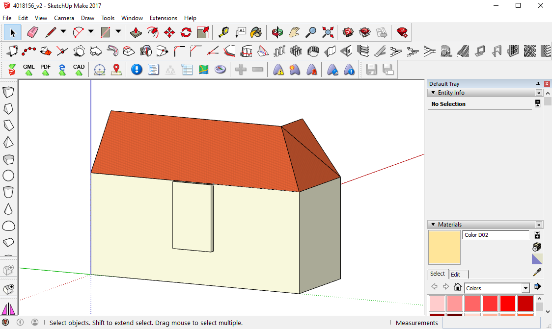
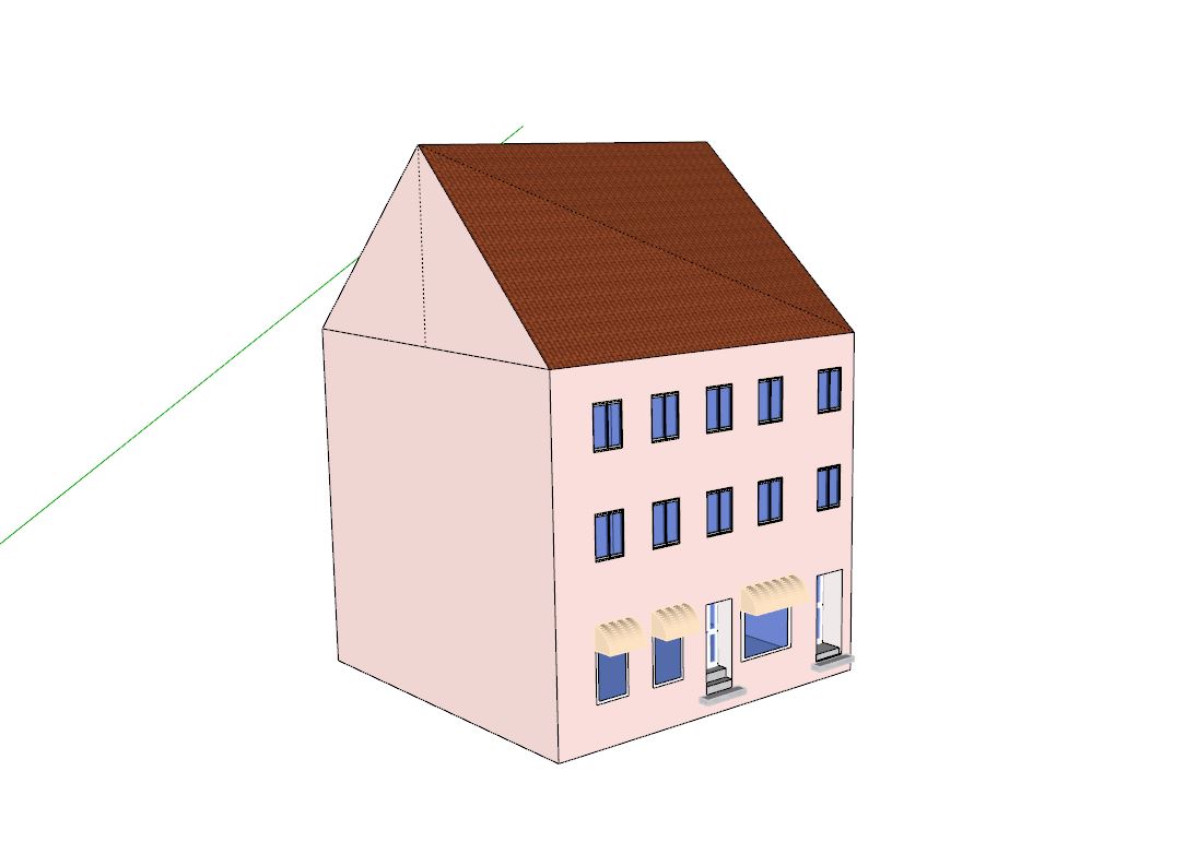
Roof
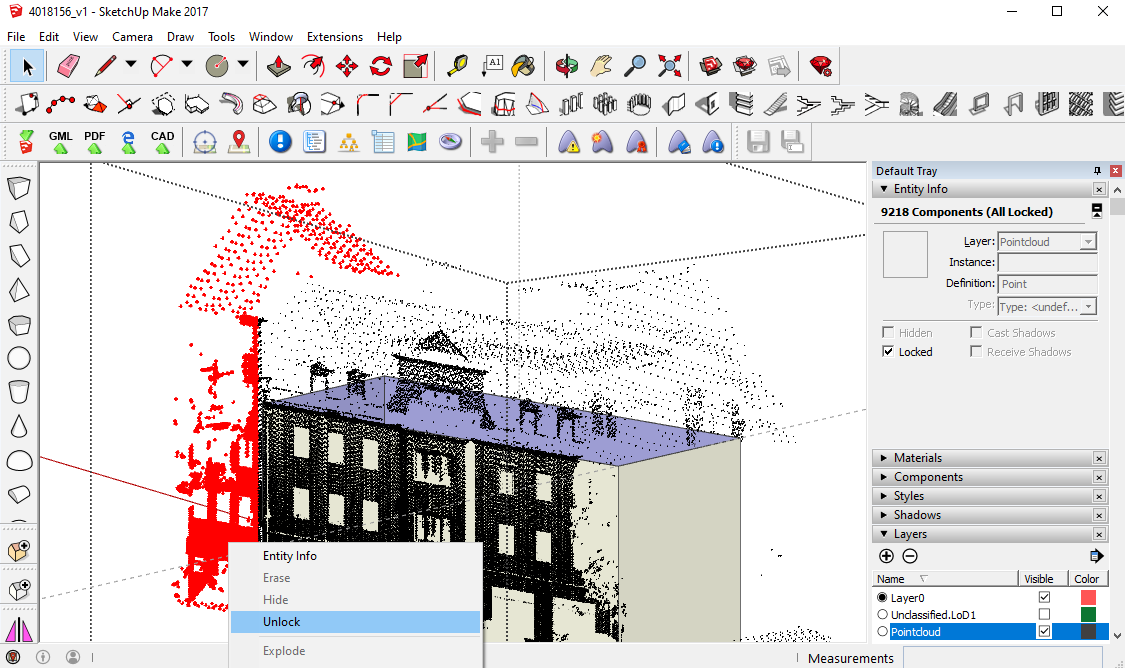
The height, angle and position of the roof can be found by means of the point cloud. One should keep in mind that the position of the roof in the point cloud can differ from its real position on the building, as the roof is scanned with an aerial scan, whereas the façade is scanned from the street. When both scans are combined, small displacements can occur. Points of other buildings can be unlocked and erased so they do not disturb.
For finding the right angle of a pitched roof, the Tape Measure Tool might help. Position a guiding line on the upper horizontal edge of one flanking wall. Check that under Camera Parallel projection and not Perspective is chosen. With the Pan tool, find a suited perspective onto the wall. With the Rotate tool, rotate the guiding line until it has the angle of the roof (the rotation should be on the wall surface). You can repeat the same for the other side. The intersection points of the guiding lines help to draw the lines of the roof.
If a roof surface is not created automatically you might have to draw another diagonal line so two triangular faces are created. If you model dormers on a roof surface afterwards, it might indeed be recommendable to have one entire and planar roof surface underneath, which does not consist of two or more triangular surfaces.
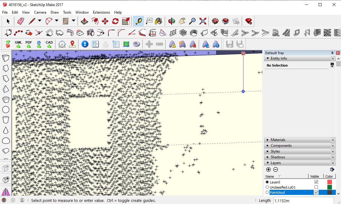
Windows
To insert windows or doors, the openings in the wall surface can be drawn first. The point cloud helps to find the position of the openings. Guiding lines can also be a support. When positioning these lines, it is important to ensure that they are lying on the wall surface (if this is the case, the blue octothorp is shown).
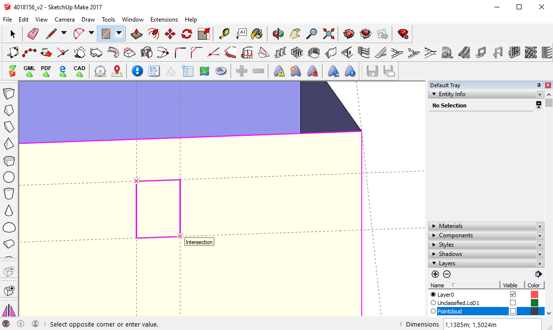
Window creation in SketchUp
To create a detailed window you can create it by yourself or use the SketchUp Warehouse. For modeling it in SketchUp, the small surfaces within the openings serve as a starting point, as they have the correct measurements. Move the surface to the outside of the building (Move tool +Strg).
The Offset tool and the Push/Pull tool might be helpful for creating the window frame e.g. Make the window a component.
After erasing the small surface within the opening you can insert the window. This or similar procedures can be applied for any other type of opening or building installations.
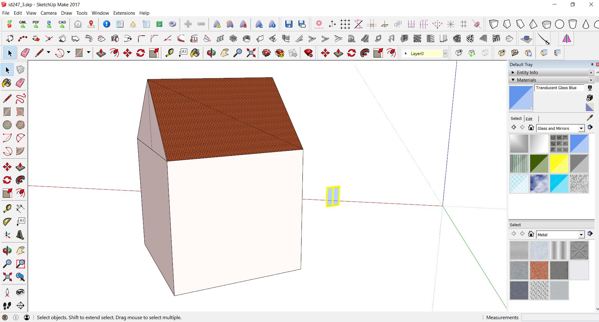
Window creation with SketchUp Warehouse
Here, an example for inserting a window from SketchUp Warehouse is given. Go to a web page of SketchUp Warehouse and find a window by typing “window” in the command line. Remember to select the right version of SketchUp (here, SketchUp 2017).
After that, you can simply open the downloaded file and select whole object and use ctrl+c and paste it into an open building project using ctrl+v.
Mostly users create such objects as Components or Groups. To assure that the local axis of the imported window is in the right place you can explode window Group/Component (similar to with building in LoD1 before). After that, you can create Component again and set the local axis - remember that window should later align with a wall or roof on which you will place it.
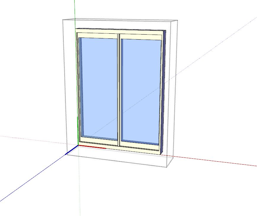
If an axis was properly assigned and a wall is created it is now possible to quickly place the window on the wall. Select the surface and then component and go to Extensions-> Chris Fullmer Tools, Component Onto Faces. Thanks to that window is aligned with a wall.
Now you can move and scale it with native Move and Scale tool. In order to cut an opening for a window the easiest way is to draw a polygon bounding the component and erase a face inside this polygon.
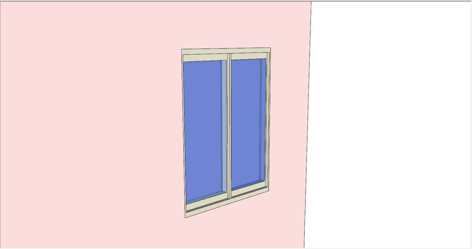
Assignment to CityGML
The exemplary windows are conformant with SketchUp and align the bounding surface properly. However, now it is important to make them semantic, CityGML Windows.
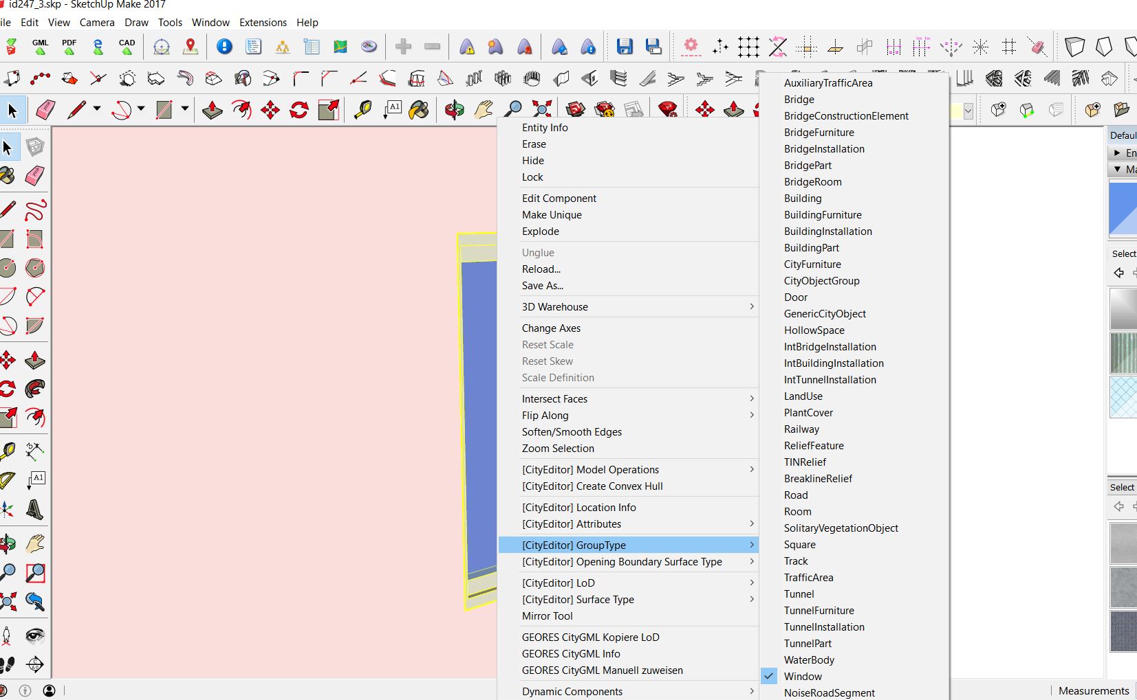
To do that Right Click-> [CityEditor.jpg GroupType ->Window. Then you have to specify what kind of opening is that - Right Click-> [CityEditor.jpg Opening Boundary Surface Type ->WallSurface and at what level of deitails Right Click-> [CityEditor.jpg LoD -> 3 as well as Right Click-> [CityEditor.jpg Surface Type ->lodXMultiSurface.
As the windows, so should all groups and components be grouped and assigned with the CityEditor plugin (Windows, BuildingInstallations, etc.) in order to be compatible with CityGML. Surfaces like walls, roofs, and ground do not have to be grouped, but also each surface needs to be assigned to specific CityGML configuration to assure CityGML validity. A useful website is sig3d.org
During the assignment, new layers are created automatically (GroundSurface.LoD3, OuterCeiling.LoD3, Unclassified.LoD3, etc.) The following table shows possible examples.
GroupType |
(Opening) Boundary Surface Type |
LoD |
Surface Type |
|
|---|---|---|---|---|
Window |
Window |
WallSurface |
3 |
lodXMultiSurface |
Door |
Door |
WallSurface |
3 |
lodXMultiSurface |
Balcony, stairs, etc. |
BuildingInstallation |
Unclassified |
3 |
lodXGeometry |
Wall Surface |
– |
WallSurface |
3 |
lodXMultiSurface |
Roof Surface |
– |
RoofSurface |
3 |
lodXMultiSurface |
Switching the different layers in SketchUp on and off can help to check whether all the components and surfaces have been assigned to CityGML configurtions already.
Material assignment
To optically represent the material and color of building objects and surfaces, the materials from the SketchUp Default Tray can be used. Further materials can be downloaded from web pages and included in SketchUp. Useful tutorials are “Top 8 Websites FOR TEXTURES AND MATERIALS for SketchUp” and “Creating CUSTOM MATERIALS in SketchUp”
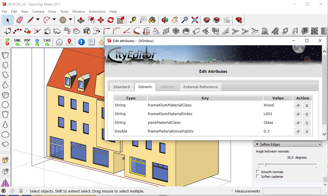
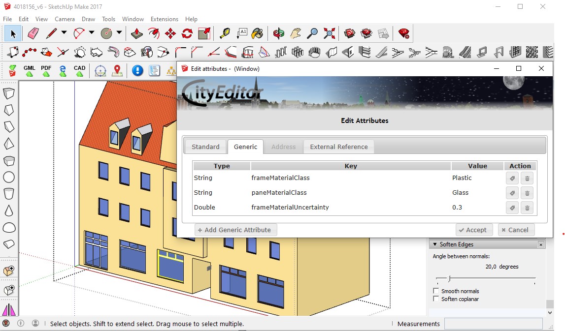
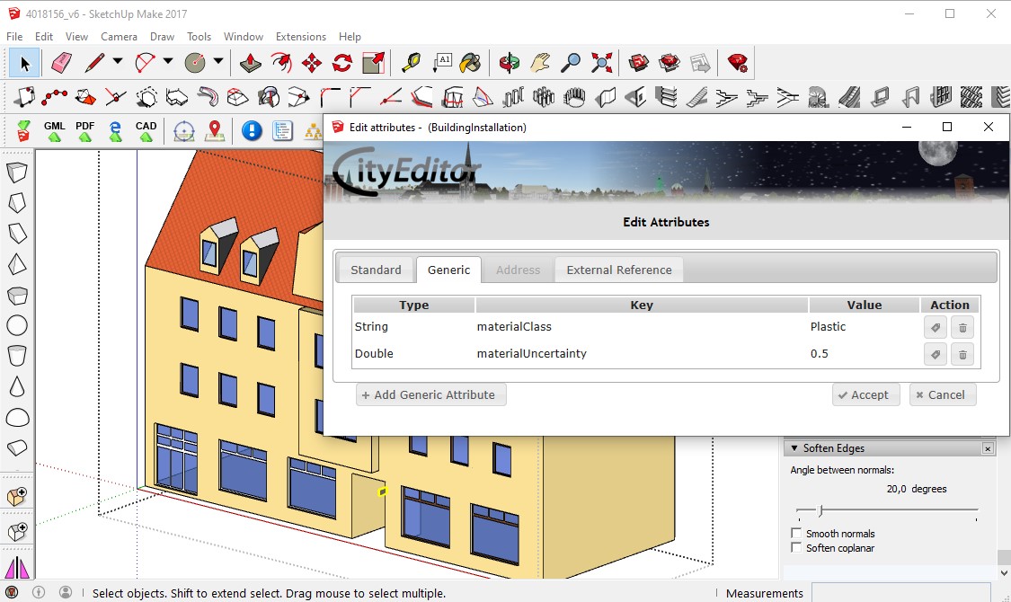
In addition to this, also generic attributes can serve for representing materials. When no field data about the exact materials are available, photos can form as baseline for the assignment.
The data of a work which investigated the reflectance of different building materials in the city of Karlsruhe are summarized in the KLUM library (https://github.com/rebeccailehag/KLUM_library/blob/master/KLUM.pdf). Another source of information about the reflectance of materials is the webpage Refractive Index (https://refractiveindex.info/).
An exemplary assignment of attributes regarding the building materials, based on these both data, is shown in the following pictures.


Closing the model
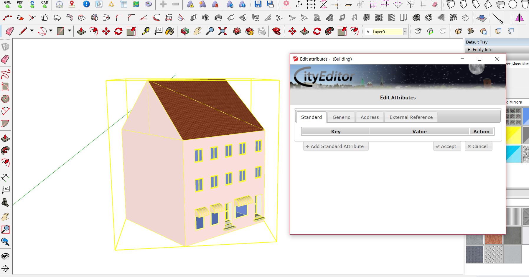
The steps for an assignment to CityGML and eventually for a material assignment have to be done for each new object within SketchUp.
Having all objects created and assigned, you can then collect them into one Building object by selecting all items and grouping them. Due to SketchUp Plugins errors, it is important to assign the Building to LoD3 again after grouping . This assures that all elements inside the group are really LoD3. To the group object you can add attributes (Right Click-> Attributes -> Edit Attributes) or paste attributes copied before from LoD1 building (Right Click-> Attributes -> Paste Attributes).
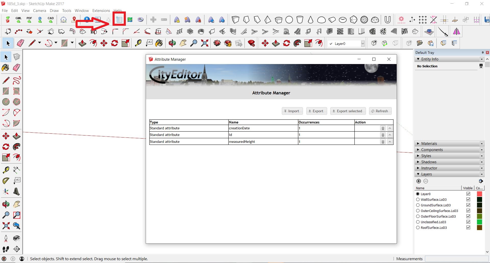
After that, it is important to erase all automatic IDs created within a group to avoid redundant IDs within a model and in comparison with other buildings. To do that, go to Attribute Manager in the main bar of SketchUp. To see all attributes click Refresh. You can control your added attributes and check whether the plugin has added something.
Attributes like PolygonID and LinearRingID should be erased before the export into CityGML.
The validation of the model structure can be done via Model Explorer located on the main SketchUp bar. Before validation, it is recommended to erase all elements and layers not relevant to the export (e.g. the point cloud or the LoD1 building). In the case of modeling LoD3 objects by using MultiSurface geometry and using Building only as a container for attributes (not for geometry) the, structure should be similar to the image below.
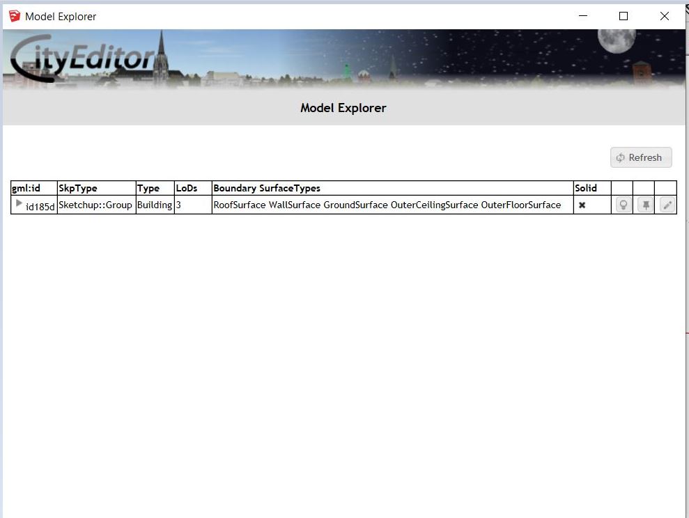
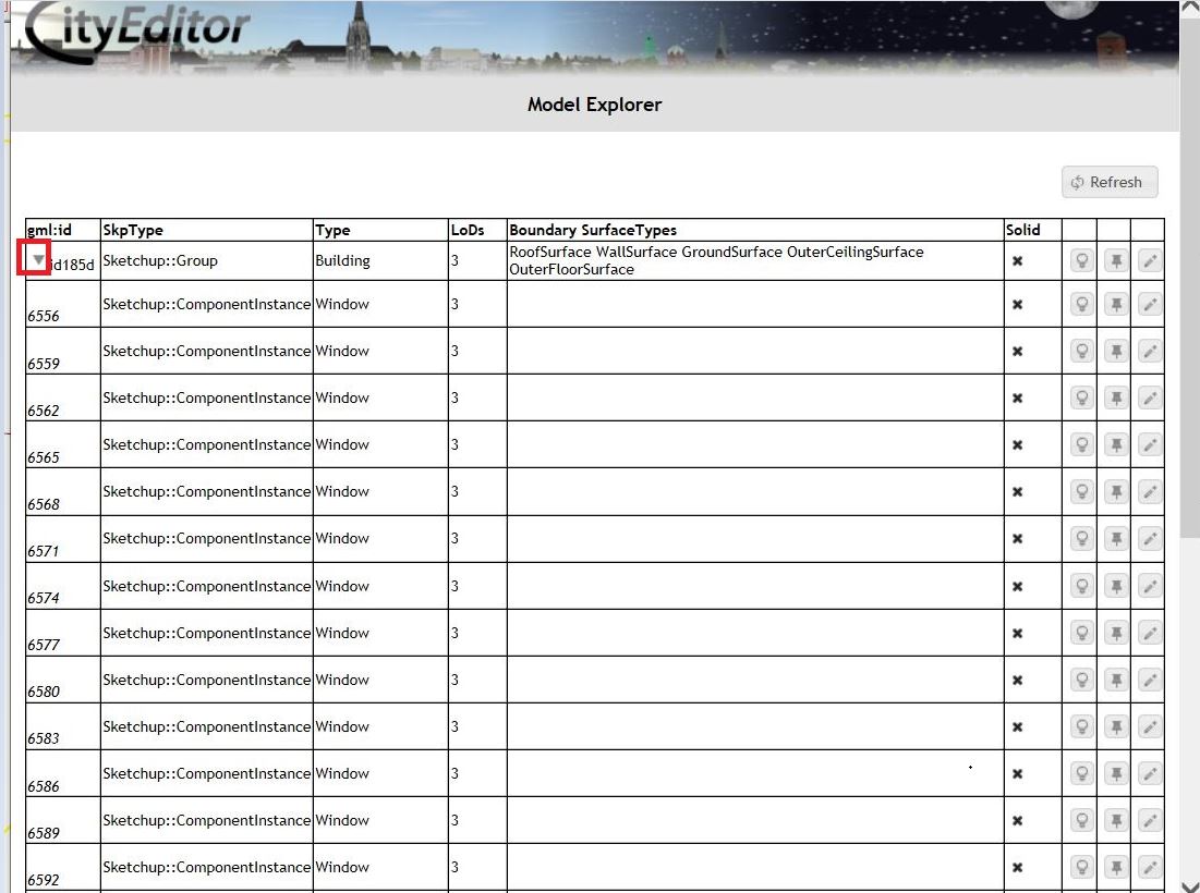
After clicking on the arrow located in the column gml:id, the structure of the object reveals.
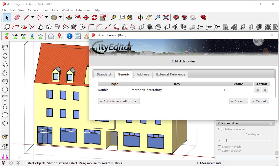
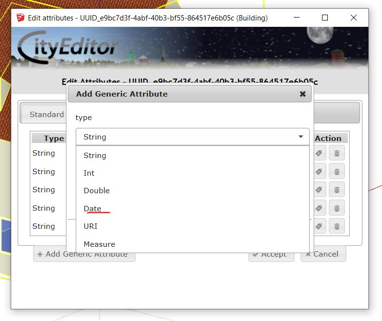
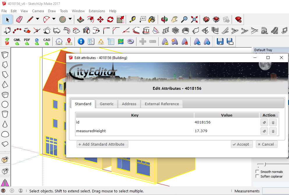
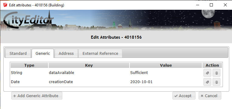
Additional attributes could be added manually to the model using Edit Attributes window. For example, one can add the Date of model creation to the edited object (be careful to use right type of date yyyy-mm-dd, i.e. 2019-09-25).
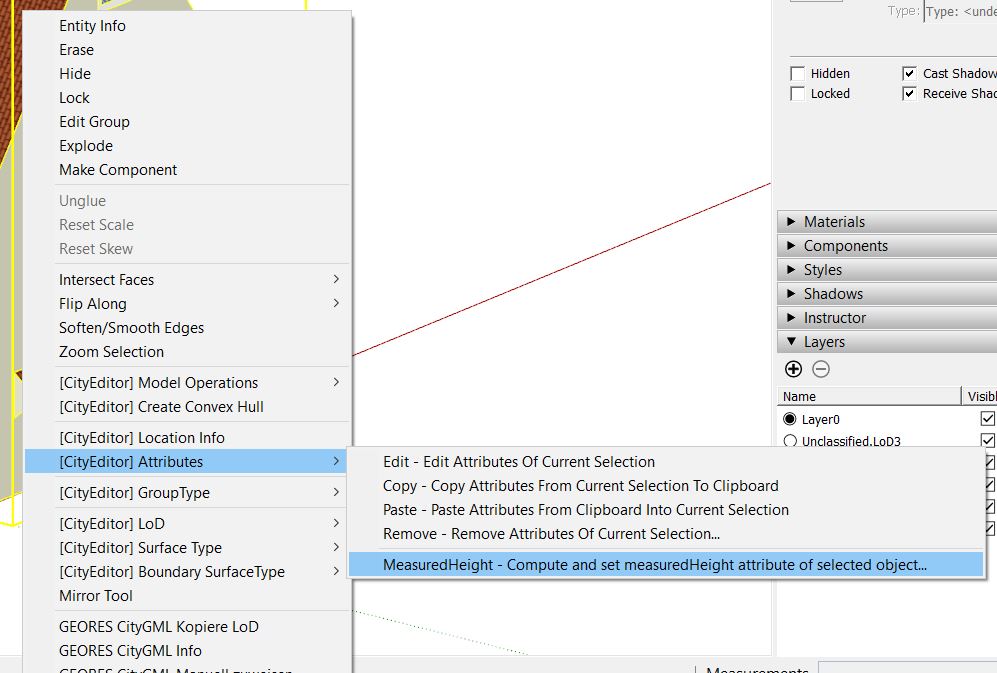
Another possibility to add a new attribute, is to use built-in plugin’s function. One can access this feature by hoovering on Attributes and then Left Click on MeasuredHeight. This step adds a new CityGML attribute with the measured relative height from the finished 3D SketchUp model.
An example of useful attributes for the modeled building is represented in the below pictures.
Additional recommendations
Some additional general recommendations for the modeling in SketchUp are:
Use shortcuts for the navigation in SketchUp and keyboard combinations for utilizing the tools.
It might be a help to switch Camera on the main SketchUp bar from Perspective to Parallel Projection.
If the cursor doesn´t catch the wanted point during a command, exit the command and use the Tape Measure Tool for guidelines in order to fix the needed point as an intersection point of guidelines and repeat the command.
It can be a help to use the Lines Tool and the Tape Measure Tool instead of the Rectangle Tool in order to draw surfaces.
When creating a component, make sure Replace selection with Component is checked.
Data export
To export files, you have to select an icon with green arrow and GML sign and select the folder to save it.
Then, the CityGML Export window is opened. You can tick here Logging to see logs while exporting.
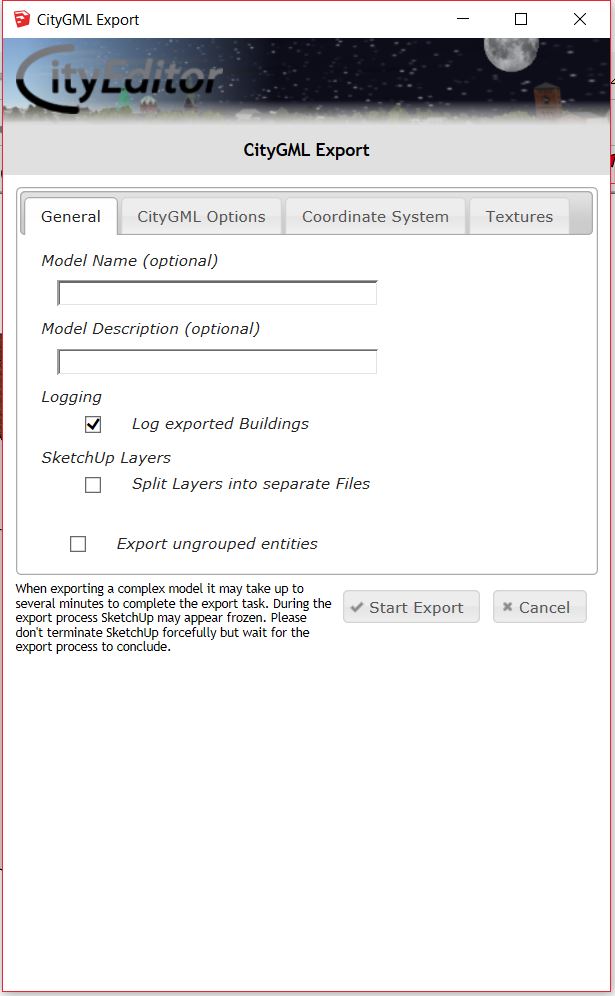
In CityGML Options section you make further configuration of exported CityGML. Very important is to type in Appearance Theme name and remember it in case of further importing it to citydb or other environments.
As ID for specific Polygons, LinearRings were deleted we have to create them again by ticking option Generate IDs for all elements this assures uniqueness. Just to be sure, we can select also Check and correct IDs thanks to that exporting algorithm will repair issues if they will appear.
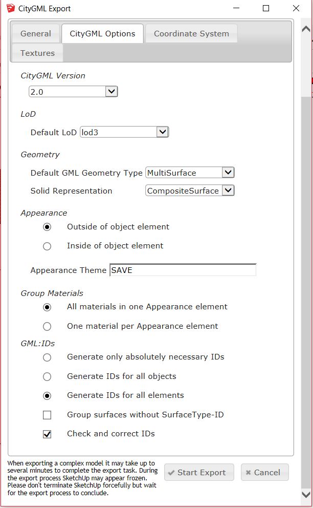
Within section Coordinate System you can check whether the coordinate system is appropriate and additionally you can apply Yaw (offset). In Textures tab you can check currently exporting materials and saving folder for those.
To continue select Start Export.
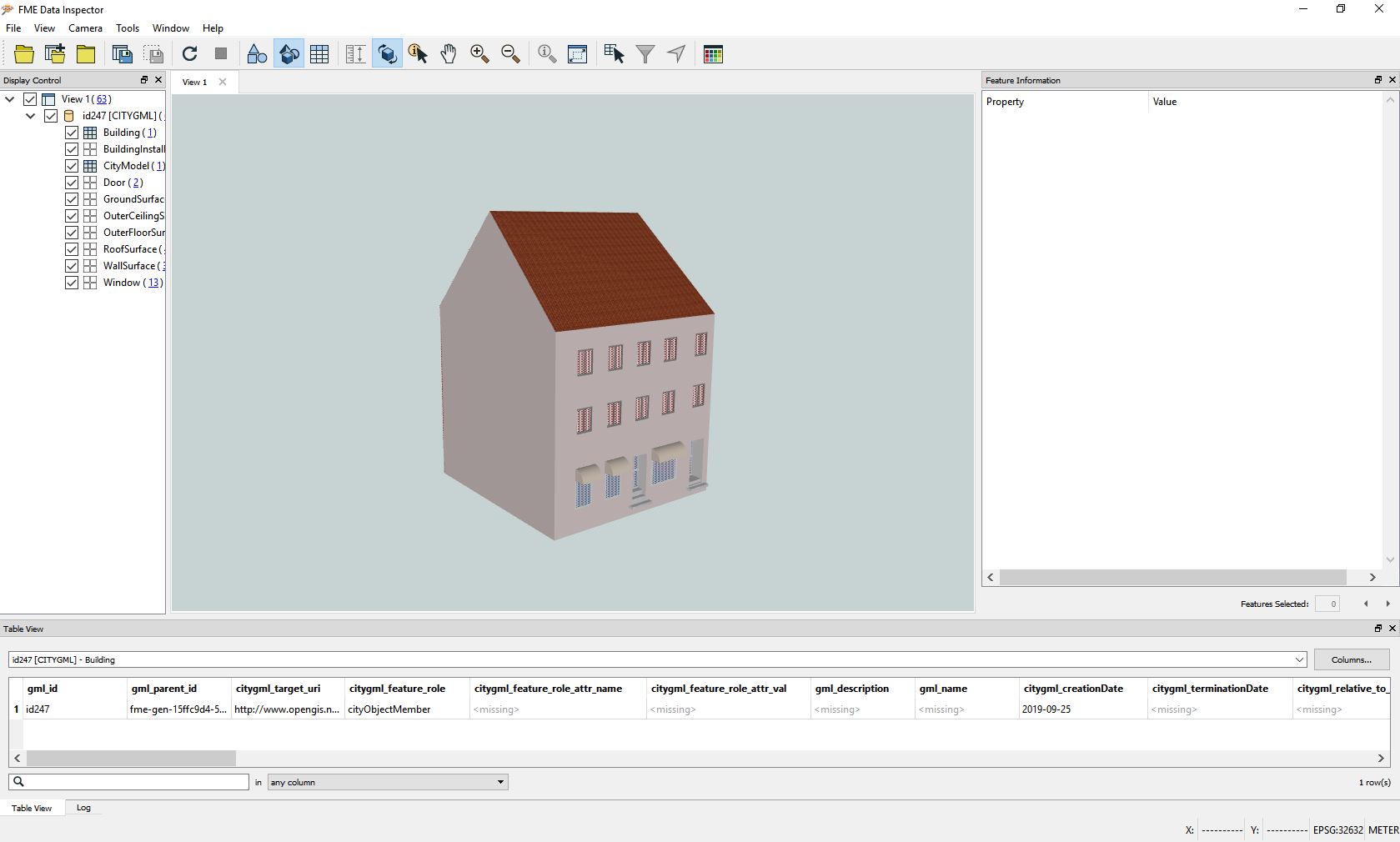
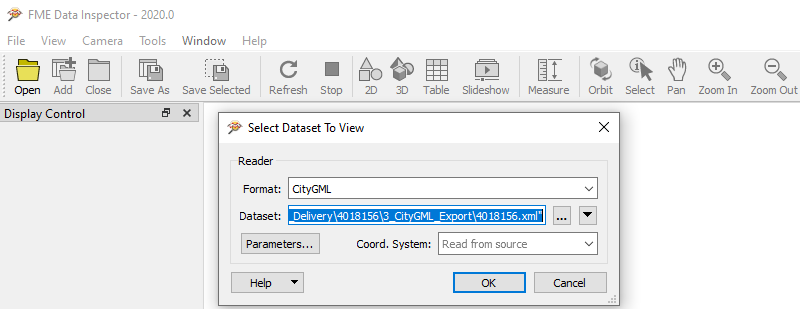
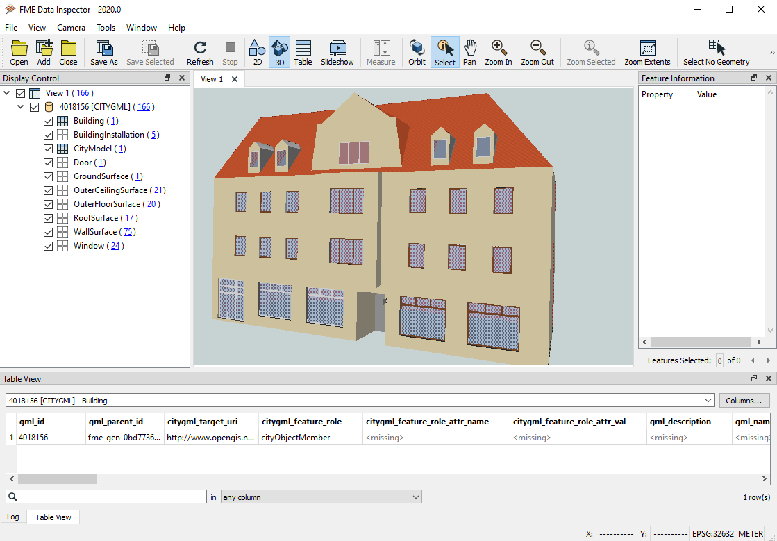
Review
To review an exported CityGML building, the FME Data Inspector can be used. Here you can e.g. revise if the components and surfaces are correctly represented and are in the correct CityGML groups. When opening a gml or xml file with the program, choose the Format CityGML.